Tech File
Argeo Listen
Argeo Listen
Electromagnetic System for High Accuracy Marine Contactless Cathodic Protection Measurements
By Johan Mattsson
Autonomous Underwater Vehicles (AUV’s) have been introduced as efficient tools for subsea pipeline inspections. It has also been demonstrated that AUVs can be used to perform contactless and continuous electric field measurements of the Cathodic Protection (CP) systems along pipelines. In this article we present a newly developed and commercialized sensor system for accurate and low noise electric field measurements. We also present electric field data along a pipeline section together with analysis and estimation of anode material consumption derived from continuous electric field measurements.
Argeo Listen – An electromagnetic receiver system
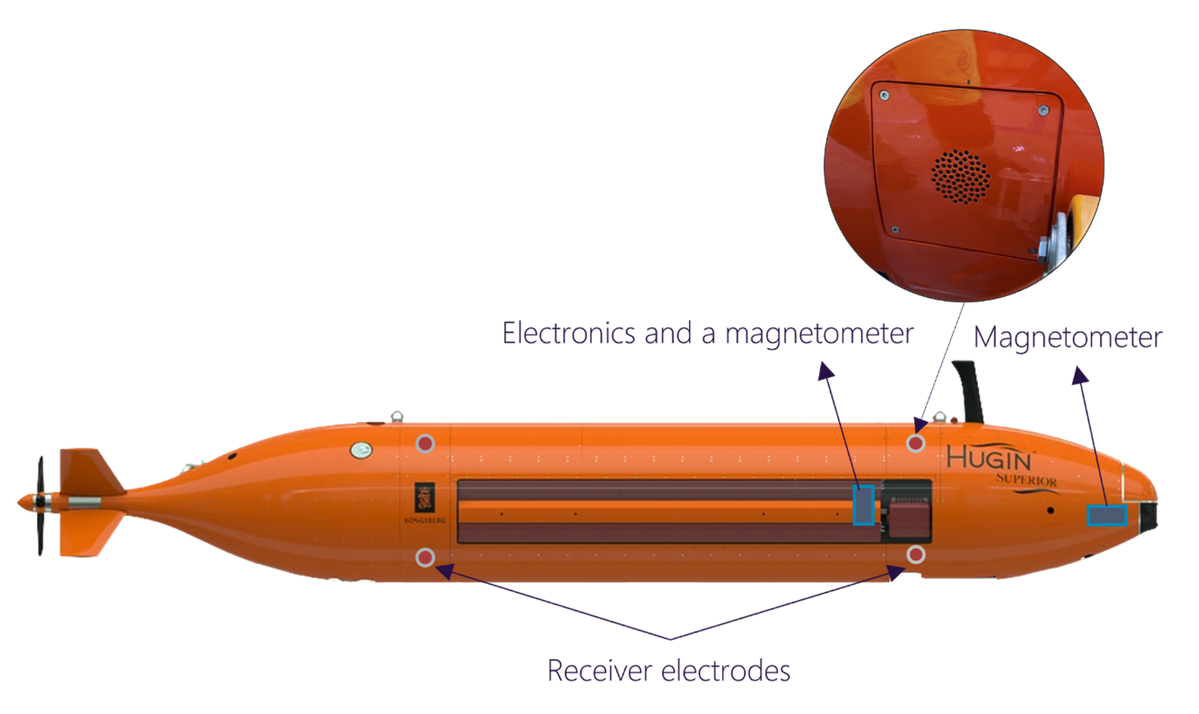
The Argeo Listen electrode system consists of eight silver/silvercloride (Ag/AgCl) electrodes mounted in flush with the hull of an AUV. Four electrodes are located in the aft and four in the front, figure 1. The mounting in flush with the hull reduces turbulence noise and prevents damages during AUV launch and recovery. Each electrode is connected through a cable inside the AUV to the acquisition electronics mounted inside a pressure bottle. The bottle is placed inside the AUV in an area chosen with the objective to minimize electromagnetic noise. The electronics bottle, cables and electrode housings and electrodes are depth-rated down to 6,000 m.
The eight electrodes are connected into eight pairs (channels) where each channel measures an electric potential field difference. The eight pairs are chosen to span the 3D space redundantly and are used to construct the full 3D electric field. The reason for this design configuration is to achieve higher accuracy in the electric field components compared to trying to measure them directly. The eight electrode pairs also give redundancy which is useful if any or several of the electrodes should degrade during a dive. The redundancy also provides additional noise suppression.
The powering of the electronics from the onboard batteries is designed to be independent on the charging levels of the batteries as well as independent on the power consumption from other onboard payloads and instruments. This is important to achieve sufficiently low noise during measurement with low influence from the AUV platform itself. As a result, the sensor system provides highly reliable and calibrated electric field measurements, with excellent signal-to-noise ratio (SNR) in CP measurements with typical noise levels less than 0.005 μV/cm. In addition, the motion stability of the AUV platform with high accuracy navigation data enable electric field measurements of sufficiently low anode output electric currents for complete CP integrity evaluation along a pipeline.
The acquisition electronics controls the sampling, digitization, and pre-processing of the EM-data before being merged with the navigation, heading, pitch, roll and environmental data as well as with magnetometer data. Automatic quality control of the nav merged EM-data then enables short turnaround time for evaluation of the CP status.
Efficient contactless CP-measurements and analysis
A working CP-system along a pipeline generates electric currents in the seawater. In particular, electric current is going out from each anode and returns into the structure at dedicated drain points or at places where the coating has been removed or damaged into bare metal. The CP-system works as a galvanic element where the electric current in the seawater generates an electric field.
An AUV equipped with the Argeo Listen electrode sensor system continuously measures the 3D electric field at a height of 5-10 m above the pipeline in a speed of 3-4 knots. This is illustrated in figure 2 where the CP resulting electric field amplitude and direction are visualized as well as the AUV on a survey line on top of the pipeline (black line on the sediment).
The electric currents going out from each anode into the seawater, are obtained from solving a linear system of equations which relates the electric current going in and out from the pipeline with the measured electric field. The low electric field noise and high accuracy of navigation data results in accurate estimations of the electric currents. The pipeline with anodes can be buried or be exposed above the seafloor. The electric field measurements and output current estimations work equally well for buried pipelines. The burial depth and positions of the anodes along the pipeline are determined directly from a combination electric and magnetic data.
Once the electric currents going out and into the pipeline have been estimated, the anode material consumption rate can be calculated. In fact, the anode output current is proportional to the material loss rate. With this information together with camera pictures, the status of the CP system can be determined. Damages are revealed and the amount of consumed anode material is determined.
The accuracy i.e. the error in the consumption rate estimation is highly dependent on the SNR. Ideally, a 30 dB SNR is necessary for sufficient accuracy. This requirement determines the maximum sail line altitude above the pipeline given a typical noise level in the measured data. With the Argeo Listen system it is possible to fly the AUV 13-15 m above the pipeline and still reach an SNR of 30 dB when the output current is 0.1 A as can be seen in figure 3. However, to resolve output currents down to 0.02 A, the recommended AUV height above the pipeline is set to 5-10 m. This altitude range also allows for good multibeam echo sounder and camera/laser coverage along the pipeline.
A CP data case
The electric field data along a pipeline shows the behavior of the CP-system. The anodes generate output electric currents into the seawater if they are active. The amount of current depends on several things like the remaining material in the anode, coating of the pipeline, i.e. return points for the electric current into the pipeline etc. The sacrificial anodes are supposed to corrode instead of the pipeline provided that electrical circuits are completed through the electrolyte, which is the seawater in this case.
When sacrificial anodes are not active, meaning no electrical current flows from them, it typically indicates that the protective coating on the pipeline is intact, preventing direct contact between the pipeline steel and the seawater. The coating acts as an insulating layer, breaking the electrical circuit necessary for corrosion to occur. Therefore, the sacrificial anodes will not corrode (or will corrode at a significantly reduced rate) because there is no pathway for the electric current to flow through the water to the pipeline.
The behavior of the electric field reveals directly where electric current is going in or out. This is most clearly seen in the E_Down component of the data. Hence, by investigating the behavior of the electric field, it can be concluded if there is any electric current going out from each anode and how the electric current is returning to the pipeline. That will tell how active the cathodic protection system is.
The AUV integrated electrode sensor system has successfully been tested on a pipeline section partly on the seafloor and partly buried. The AUV was sailing 5-6 m above the pipeline section in 3 knots speed. Multiple runs back and forth were conducted to check for repeatability and consistency in the acquired data. The vertical component of the electric field from two of the runs is shown in the top graph of figure 4. The measurements can be performed at any speed the AUV can do.
The signal-to-noise ratio in the signal peaks above the anodes, the black dots, is high (about 30 dB). The repeatability between the runs is good with low noise in the data between the peaks. This data accuracy makes it possible to determine the anode output currents with high precision and then enabling good estimations of the anode consumption rates with error bars shown in the bottom graph of figure 4.
The acquired electric field data, the resulted output currents and estimated anode material consumption rates are integrated with camera images, multibeam and synthetic aperture sonar data for a complete pipeline analysis. An example of this is shown in figure 5 where all data from a pipeline survey are merged and displayed in 3D using the Argeo Scope cloud based software. The merge of the CP measurements with other data in 3D enables fast and efficient evaluation of the complete pipeline integrity.
In summary, it can be concluded that the AUV with the implemented Argeo Listen electrode system together with accurate navigation data facilities efficient and accurate investigations of pipeline CP-systems on or below the seafloor.
About the Author
Johan Mattsson (PhD) is currently chief Physicist in Argeo. He develops electromagnetic technology for underwater applications using vehicles like AUVs and ROVs.
